利用 Cisco Packet Tracer 进行组网实验 2
前两个是设计题,后几个是应用题。
配置Serial静态路由
画出基本的网络拓扑,然后进行配置。
放置2台
Router-PT,2台PT-PCPC0和PC1使用铜交叉线连接到Router0Router0和Router1使用串行DCE线连接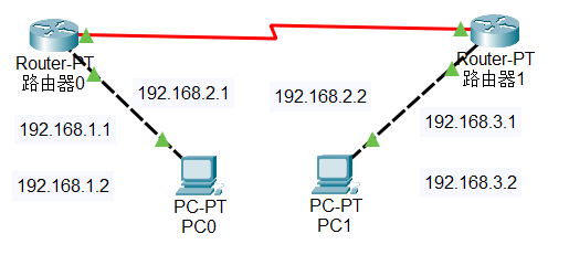
配置
Router的IP地址1
2
3
4
5enable
config -t
int f0/0
ip address [IP] [MASK]
no shutdown路由器0左边配置为192.168.1.0网段
路由器0至路由器1配置为192.168.2.0网段
路由器1右边配置为192.168.3.0网段
路由器0 f0/0 为
192.168.1.1/24
路由器0 s2/0 为192.168.2.1/24
路由器1 f0/0 为192.168.3.1/24
路由器1 s2/0 为192.168.2.2/24使用IP配置工具分别配置PC0和PC1的IP和网关
PC0为192.168.1.2/24网关为192.168.1.1PC1为192.168.3.2/24网关为192.168.3.1同步串行DCE线的时钟
在路由器与路由器之间使用串行DCE线连接时,需要同步时钟
鼠标指向线两端的三角形,会浮出时钟图标,则该路由器需要配置时钟
1
2
3
4enable
config -t
int s2/0
clock rate 64000配置静态路由
在路由器中配置到达下一跳的路由
1
2
3enable
config -t
ip route [目标网段] [子网掩码] [下一跳地址]路由器0
1
ip route 192.168.3.0 255.255.255.0 192.168.2.2
路由器1
1
ip route 192.168.1.0 255.255.255.0 192.168.2.1
模拟通信
在
PC0中 pingPC1,查看是否能够通信在模拟器中查看数据包的传输过程
静态路由是在路由器上手动配置的路由,用于指定到达目的网络的下一跳地址。
两层交换机路由
画出基本的网络拓扑,然后进行配置。
放置2台
2960-24交换机,4台PT-PC,1台1841路由器使用铜直通线连接交换机和电脑以及路由器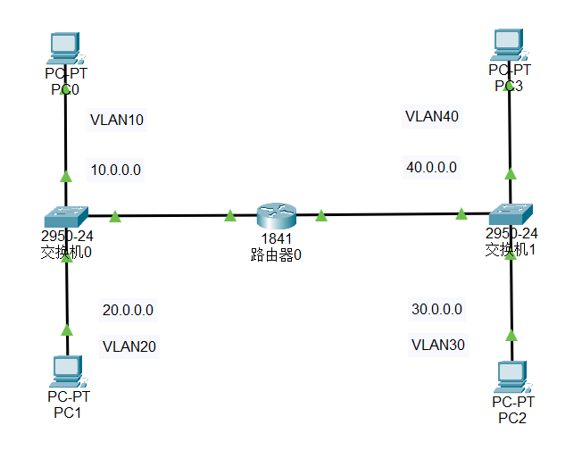
PC0 连接到
Switch0的f0/1端口
PC1 连接到Switch0的f0/2端口
PC2 连接到Switch1的f0/1端口
PC3 连接到Switch1的f0/2端口Switch0的f0/3端口连接到Router0的f0/0端口Switch1的f0/3端口连接到Router0的f0/1端口配置
PC的IP地址PC0: 10.0.0.2/8 网关 10.0.0.1
PC1: 20.0.0.2/8 网关 20.0.0.1
PC2: 30.0.0.2/8 网关 30.0.0.1
PC3: 40.0.0.2/8 网关 40.0.0.1Switch0和Switch1划分 VLANSwitch0:1
2
3
4
5
6
7
8
9
10
11
12
13
14
15
16
17
18enable
config -t
vlan 10
name vlan10
exit
vlan 20
name vlan20
exit
int f0/1
switchport mode access
switchport access vlan 10
exit
int f0/2
switchport mode access
switchport access vlan 20
exit
int f0/3
switchport mode trunkSwitch1:1
2
3
4
5
6
7
8
9
10
11
12
13
14
15
16
17
18enable
config -t
vlan 30
name vlan30
exit
vlan 40
name vlan40
exit
int f0/1
switchport mode access
switchport access vlan 30
exit
int f0/2
switchport mode access
switchport access vlan 40
exit
int f0/3
switchport mode trunk配置路由
1
2
3
4
5
6
7
8
9
10
11
12
13
14
15
16
17
18
19
20
21
22
23
24
25
26
27
28enable
config -t
int f0/0
no shutdown
exit
int f0/1
no shutdown
exit
int f0/0.1
encapsulation dot1Q 10
ip address 10.0.0.1 255.0.0.0
no shutdown
exit
int f0/0.2
encapsulation dot1Q 20
ip address 20.0.0.1 255.0.0.0
no shutdown
exit
int f0/1.3
encapsulation dot1Q 30
ip address 30.0.0.1 255.0.0.0
no shutdown
exit
int f0/1.4
encapsulation dot1Q 40
ip address 40.0.0.1 255.0.0.0
no shutdown
exit模拟模式中使用 IMCP 协议进行 ping 测试
PC0 ping
PC1 ping
PC2 ping
PC3 ping
三层交换机双臂路由
画出基本的网络拓扑,然后进行配置。
放置2台
2960-24交换机,4台PT-PC,1台3560-24PS三层交换机使用铜直通线连接交换机和电脑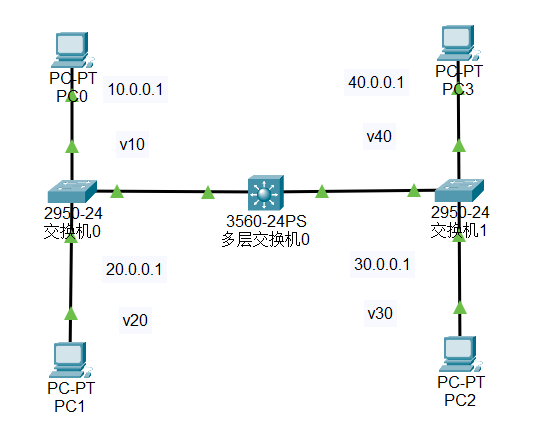
PC0 连接到
Switch0的f0/1端口
PC1 连接到Switch0的f0/2端口
PC2 连接到Switch1的f0/1端口
PC3 连接到Switch1的f0/2端口Switch0的f0/3端口连接到MultilayerSwitch0的f0/1端口Switch1的f0/3端口连接到MultilayerSwitch0的f0/2端口配置
PC的IP地址PC0: 10.0.0.2/8 网关 10.0.0.1
PC1: 20.0.0.2/8 网关 20.0.0.1
PC2: 30.0.0.2/8 网关 30.0.0.1
PC3: 40.0.0.2/8 网关 40.0.0.1MultilayerSwitch0划分 VLAN1
2
3
4
5
6
7
8
9
10
11
12
13
14
15
16
17
18
19
20
21
22
23enable
config -t
vlan 10
exit
vlan 20
exit
vlan 30
exit
vlan 40
exit
int vlan 10
ip address 10.0.0.1 255.0.0.0
exit
int vlan 20
ip address 20.0.0.1 255.0.0.0
exit
int vlan 30
ip address 30.0.0.1 255.0.0.0
exit
int vlan 40
ip address 40.0.0.1 255.0.0.0
exit
ip routingSwitch0和Switch1划分 VLANSwitch0:1
2
3
4
5
6
7
8
9
10
11
12
13
14
15
16
17
18enable
config -t
vlan 10
name vlan10
exit
vlan 20
name vlan20
exit
int f0/1
switchport mode access
switchport access vlan 10
exit
int f0/2
switchport mode access
switchport access vlan 20
exit
int f0/3
switchport mode trunkSwitch1:1
2
3
4
5
6
7
8
9
10
11
12
13
14
15
16
17
18
19enable
config -t
vlan 30
name vlan30
exit
vlan 40
name vlan40
exit
int f0/1
switchport mode access
switchport access vlan 10
exit
int f0/2
switchport mode access
switchport access vlan 20
exit
int f0/3
switchport mode trunk
exit模拟模式中使用 IMCP 协议进行 ping 测试
PC0 ping
PC1 ping
PC2 ping
PC3 ping实体环境中测试
自动 DHCP 配置
画出基本的网络拓扑,然后进行配置。
放置2台
PT-Router路由器,2台PT-PC
使用铜交叉线连接Router和PC
使用串行DCE线连接两台Router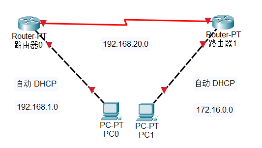
PC0 连接到
Router0的f0/0端口
PC1 连接到Router1的f0/0端口Router0的s2/0连接到Router1的s2/0端口配置
Router的IP地址Router0:1
2
3
4
5
6
7
8
9
10enable
config -t
int f0/0
ip address 192.168.1.1 255.255.255.0
no shutdown
exit
int s2/0
ip address 192.168.20.1 255.255.255.0
no shutdown
exitRouter1:1
2
3
4
5
6
7
8
9
10enable
config -t
int f0/0
ip address 172.16.0.1 255.255.0.0
no shutdown
exit
int s2/0
ip address 192.168.20.2 255.255.255.0
no shutdown
exitDCE 线配置
找到有时钟标记的
Router,在该Router上配置DCE线Router:1
2
3
4
5enable
config -t
int s2/0
clock rate 64000
exit配置
Router之间的路由Router0:1
2
3
4enable
config -t
ip route 172.16.0.0 255.255.0.0 192.168.20.2
exitRouter1:1
2
3
4enable
config -t
ip route 192.168.1.0 255.255.255.0 192.168.20.1
exit在
Router0上配置DHCP服务1
2
3
4
5
6
7enable
config -t
ip dhcp pool LAN1
network 192.168.1.0 255.255.255.0
default-router 192.168.1.1
dns-server 1.1.1.1
exit在
Router1上配置DHCP服务1
2
3
4
5
6
7enable
config -t
ip dhcp pool LAN2
network 172.16.0.0 255.255.0.0
default-router 172.16.0.1
dns-server 1.1.1.1
exitPC 配置
PC0:
DHCP
PC1:DHCP测试
PC0 ping PC1
中继代理 DHCP 配置
画出基本的网络拓扑,然后进行配置。
放置2台
PT-Router路由器,2台PT-PC
使用铜交叉线连接Router和PC
使用串行DCE线连接两台Router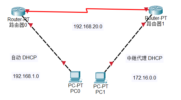
PC0 连接到
Router0的f0/0端口 网段 192.168.1.0
PC1 连接到Router1的f0/0端口 网段 172.16.0.0Router0的s2/0连接到Router1的s2/0端口 网段 192.168.20.0Router0自动 DHCP 服务,Router1中继代理 DHCP 服务配置
Router的IP地址Router0:1
2
3
4
5
6
7
8
9
10enable
config -t
int f0/0
ip address 192.168.1.1 255.255.255.0
no shutdown
exit
int s2/0
ip address 192.168.20.1 255.255.255.0
no shutdown
exitRouter1:1
2
3
4
5
6
7
8
9
10enable
config -t
int f0/0
ip address 172.16.0.1 255.255.0.0
no shutdown
exit
int s2/0
ip address 192.168.20.2 255.255.255.0
no shutdown
exitDCE 线配置
找到有时钟标记的
Router,在该Router上配置DCE线Router:1
2
3
4
5enable
config -t
int s2/0
clock rate 64000
exit配置
Router之间的路由Router0:1
2
3
4enable
config -t
ip route 172.16.0.0 255.255.0.0 192.168.20.2
exitRouter1:1
2
3
4enable
config -t
ip route 192.168.1.0 255.255.255.0 192.168.20.1
exit在
Router0上配置DHCP服务1
2
3
4
5
6
7
8
9
10
11
12enable
config -t
ip dhcp pool LAN1
network 192.168.1.0 255.255.255.0
default-router 192.168.1.1
dns-server 1.1.1.1
exit
ip dhcp pool LAN2
network 172.16.0.0 255.255.0.0
default-router 172.16.0.1
dns-server 1.1.1.1
exit在
Router1上配置 中继代理DHCP服务1
2
3
4
5
6enable
config -t
service dhcp
int f0/0
ip helper-address 192.168.20.1
exitip helper-address用于将广播的 DHCP 请求转发到指定的 DHCP 服务器测试
PC0 ping PC1
访问控制列表
画出基本的网络拓扑,然后进行配置。
放置一台
1841路由器,两台PT-PC,1台Server-PT服务器使用铜交叉线连接交换机和电脑以及服务器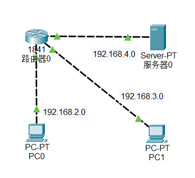
对Router0进行改装,增加2个WIC-1NET模块,或者WIC-4ESW模块,本次使用WIC-4ESW模块
PC0 连接到Router0的fa0/0/0端口
PC1 连接到Router0的fa0/0/1端口Server0连接到Router0的f0/0端口配置
PC的IP地址PC0: 192.168.2.2/24 网关 192.168.2.1
PC1: 192.168.3.2/24 网关 192.168.3.1
Server0: 192.168.4.2/24 网关 192.168.4.1配置路由
1
2
3
4
5
6
7
8
9
10
11
12
13
14
15
16
17
18
19
20
21
22
23
24
25
26enable
config -t
vlan 10
exit
vlan 20
exit
int f0/0/0
switchport mode access
switchport access vlan 10
no shutdown
exit
int f0/0/1
switchport mode access
switchport access vlan 20
no shutdown
exit
int vlan 10
ip address 192.168.2.1 255.255.255.0
exit
int vlan 20
ip address 192.168.3.1 255.255.255.0
exit
int f0/0
ip address 192.168.4.1 255.255.255.0
no shutdown
exit在
Router0上配置拒绝192.168.2.0网段的机子访问服务器。(ftp ping web-server 都不通)1
2
3
4enable
configure terminal
access-list 101 deny ip 192.168.2.0 0.0.0.255 host 192.168.4.2
access-list 101 permit ip any any在
Router0上配置禁止192.168.3.0网段的机子访问服务器的HTTP服务(http://192.168.4.2),其他服务正常(可以 ftp ping)。1
2
3
4enable
config -t
access-list 102 deny tcp 192.168.3.0 0.0.0.255 host 192.168.4.2 eq www
access-list 102 permit ip any any在
Router0启用访问控制列表1
2
3
4
5enable
config -t
int f0/0
ip access-group 101 out
ip access-group 102 outin 表示进入接口,out 表示出接口,服务器在 f0/0 端口,是出接口,是外部访问,所以使用 out
查看访问控制列表
1
show access-list
实体环境中测试
PC0 ping
PC1 ping
PC1 访问Server0的HTTP服务(使用 Web 浏览器访问192.168.4.2)
注意事项
相同设备用交叉线连接,不同设备用直通线连接。比如
PC和Router之间用交叉线连接,Router之间用直通线连接。PC 和交换机之间用直通线连接。访问控制列表时,
permit表示允许,deny表示拒绝访问控制列表时,
in表示进入接口,out表示出接口访问控制列表时,
access-list后面的数字表示访问控制列表的编号多层交换机路由时,
no switchport表示将端口转换为路由端口三层交换机双臂路由时,
ip routing表示开启路由功能路由器的
FastEthernet端口用于连接PC,Serial端口用于连接其他路由器。在连接两台路由器时,需要使用
DCE线连接,并且需要配置时钟。