利用 Cisco Packet Tracer 进行组网实验 1
安装和汉化
- 下载安装包官网下载地址:Cisco Packet Tracer
- 安装
- 汉化
![]()
Cisco-Packet-Tracer-Chinese
遵循项目中的 README.md 进行操作即可。
组建对等网
画出基本的网络拓扑,然后进行配置。
放置一台
2950-24交换机,两台PT-PC
使用铜直通线连接交换机和电脑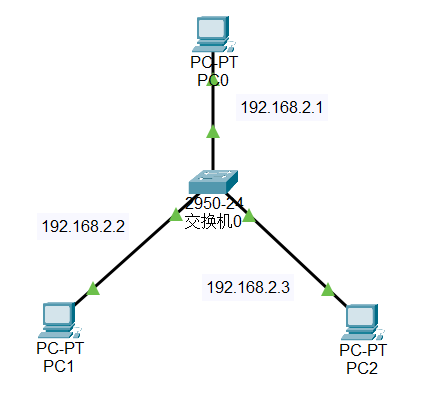
在配置页面配置 PC IP 地址
分别为192.168.2.1/192.168.2.2/192.168.2.3
ping 测试
在 PC1 中 ping PC2 和 PC3,查看是否能够通信
常见思科交换机命令:
1 | enable # 进入特权模式 |
跨交换机VLAN通信
画出基本的网络拓扑,然后进行配置。
放置2台
2950-24交换机,4台PT-PCPC1和PC2连接到Switch0,PC3和PC4连接到Switch1PC与Switch之间使用铜直通线连接Switch之间使用交叉线连接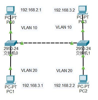
配置
PC的IP地址PC0为192.168.2.1PC1为192.168.3.1PC2为192.168.2.2PC3为192.168.3.2ping 测试
在
PC0中 pingPC1和PC2,查看是否能够通信配置
VLAN两台交换机分别配置
VLAN,并将PC分配到不同的VLAN中1
2
3
4
5enable
config -t
int f0/1
switchport mode access # 设置端口模式为访问模式
switchport access vlan 10 # 设置端口所属的 VLAN1
2
3int f0/2
switchport mode access
switchport access vlan 20配置
Trunk端口两台交换机之间的连接端口配置为
Trunk端口1
2int f0/3
switchport mode trunk有没有配置成功可以在图形界面上查看端口
ping 测试
在
PC0中 pingPC2,查看是否能够通信在PC1中 pingPC3,查看是否能够通信模拟测试
在
PC0中使用ping命令,在模拟器中查看数据包的传输过程(仅查看 ICMP 以提升效率)
trunk 端口是用来连接两台交换机的,可以传输多个 VLAN 的数据,而 access 端口只能传输一个 VLAN 的数据。
路由器和网关
画出基本的网络拓扑,然后进行配置。
放置1台
1841-Router,2台PT-PCPC0和PC1使用铜交叉线连接到Router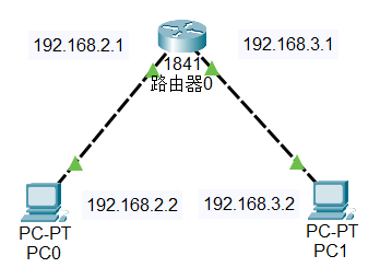
配置
Router的IP地址FastEthernet0/0 为
192.168.2.1
FastEthernet0/1 为192.168.3.1配置
PC的IP地址PC0为192.168.2.2PC1为192.168.3.2配置
PC的 网关PC0的网关为192.168.2.1PC1的网关为192.168.3.1ping 测试在
PC0中 pingPC1,查看是否能够通信
路由器是用来连接不同网络的设备,可以实现不同网络之间的通信。网关(Gateway)是用来连接不同网络的设备,可以实现不同网络之间的通信。
单臂路由
画出基本的网络拓扑,然后进行配置。
放置一台
2950-24交换机,两台PT-PC
使用铜直通线连接交换机和电脑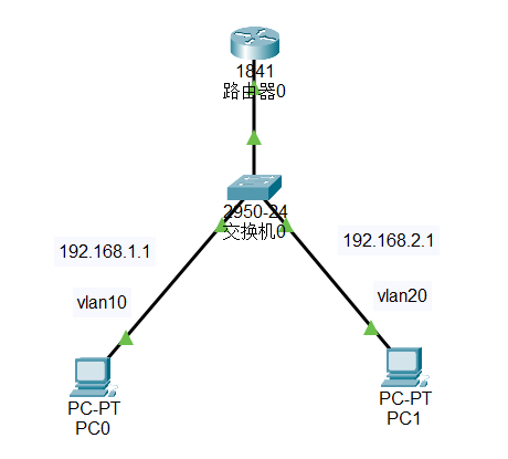
PC0 连接到
Switch0的f0/1端口
PC1 连接到Switch0的f0/2端口Switch0的f0/3端口连接到Router0的f0/0端口配置
PC的IP地址PC0: 192.168.1.1/24 网关 192.168.1.2
PC1: 192.168.2.1/24 网关 192.168.2.2交换机划分 VLAN
1
2
3
4
5
6
7
8
9
10
11
12
13
14
15
16
17
18enable
config -t
vlan 10
name vlan10
exit
vlan 20
name vlan20
exit
int f0/1
switchport mode access
switchport access vlan 10
exit
int f0/2
switchport mode access
switchport access vlan 20
exit
int f0/3
switchport mode trunk配置路由
1
2
3
4
5
6
7
8
9
10
11
12
13
14
15enable
config -t
int f0/0
no shutdown
exit
int f0/0.1
encapsulation dot1Q 10
ip address 192.168.1.2 255.255.255.0
exit
int f0/0.2
encapsulation dot1Q 20
ip address 192.168.2.2 255.255.255.0
exit
ip routing
show ip route模拟模式中使用 IMCP 协议进行 ping 测试
PC0 ping
PC1 ping实体环境中测试
多层交换机路由
画出基本的网络拓扑,然后进行配置。
放置两台
PT-PC,1台3560-24PS多层交换机使用铜直通线连接交换机和电脑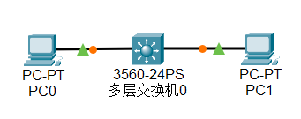
PC0 连接到
MultilayerSwitch0的f0/1端口
PC1 连接到MultilayerSwitch0的f0/2端口配置
PC的IP地址PC0: 192.168.1.1/24 网关 192.168.1.2
PC1: 192.168.2.1/24 网关 192.168.2.2MultilayerSwitch0配置1
2
3
4
5
6
7
8
9
10
11
12
13enable
config -t
int f0/1
no switchport
ip address 192.168.1.2 255.255.255.0
exit
int f0/2
no switchport
ip address 192.168.2.2 255.255.255.0
exit
ip routing
exit
show ip route模拟模式中使用 IMCP 协议进行 ping 测试
PC0 ping
PC1 ping实体环境中测试
静态NAT配置
画出基本的网络拓扑,然后进行配置。
放置一台
1841路由器,3台PT-PC,1台2950-24交换机使用铜交叉线连接Router0和PC0
使用铜直通线连接Switch0和PC1,PC2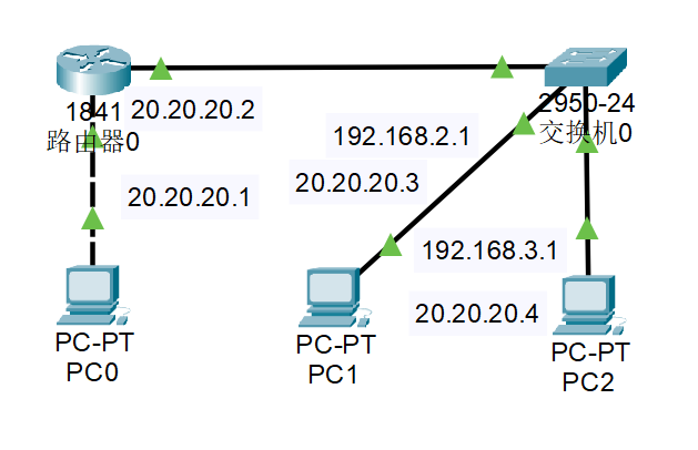
PC0 连接到
Router0的f0/0端口
PC1 连接到Switch0的f0/2端口
PC1 连接到Switch0的f0/3端口Switch0的f0/1端口连接到Router0的f0/1端口配置
PC的IP地址PC0: 20.20.20.1 网关 20.20.20.2
PC1: 192.168.2.1 网关 192.168.2.2
PC2: 192.168.3.1 网关 192.168.3.2交换机划分 VLAN
1
2
3
4
5
6
7
8
9
10
11
12
13
14
15
16
17enable
config -t
vlan 10
name vlan10
exit
vlan 20
name vlan20
exit
int f0/1
switchport mode trunk
int f0/2
switchport mode access
switchport access vlan 10
int f0/3
switchport mode access
switchport access vlan 20
exit配置路由
1
2
3
4
5
6
7
8
9
10
11
12
13
14
15
16
17
18enable
config -t
int f0/0
ip address 20.20.20.2
no shutdown
exit
int f0/1
no shutdown
exit
int f0/1.1
encapsulation dot1Q 10
ip address 192.168.2.2 255.255.255.0
exit
int f0/1.2
encapsulation dot1Q 20
ip address 192.168.3.2 255.255.255.0
exit
ip routing在路由器配置静态NAT
1
2
3
4
5
6
7
8
9
10
int f0/0
ip nat outside
exit
int f0/1
ip nat inside
exit
ip nat inside source static 192.168.2.1 20.20.20.3
ip nat inside source static 192.168.3.1 20.20.20.4
exit
show ip nat translations测试
在内网任意一台
PC上 ping 外网PC0
注意事项1
交换机的
Trunk端口用于连接两台交换机,可以传输多个VLAN的数据。交换机的
Access端口用于连接PC,只能传输一个VLAN的数据。通常,路由器的端口默认是关闭的,需要手动打开。
静态路由是在路由器上手动配置的路由,用于指定到达目的网络的下一跳地址。
NAT 配置时,
inside表示内网,outside表示外网配置
NAT时,inside的IP地址是内网IP地址,outside的IP地址是外网IP地址